TEG and its staff have provided management, oversight and engineering services for more than 178 miles of district energy pipelines. We have directly provided services for developed, design and construction services for more than 50 miles of new district energy pipeline construction. A few of the more recent projects follow:
Berea College; Berea, KY
In conjunction with the construction of a new 1,400 ton & 40 mmbtuh central plant, 10,600 trench-feet of CW & HW distribution system.
Detroit Thermal; Detroit, MI
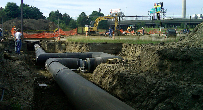
Major distribution system extension , 7,200 LF of HP steam distribution system major manufacturing facility and new customer service connection.
Detroit Thermal; Detroit, MI
New 30,000 mmBTU/h customer service, relocate 120 trench-feet of 20″ HP steam main and 400 trench-feet of 8″ HP main with service connection.
Entergy Thermal, LLC; New Orleans, LA
New customer connection to server the LCRC to deliver 35,000 pph steam and 2,400 tons cooling, 200 trench feet steam, condensate & chilled water distribution system expansion.
EnWave USA; New Orleans, LA
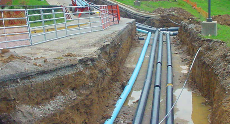
As part of a major district energy system expansion to server the UMC medical campus, 2,990 trench feet of steam & condensate, 3,335 trench-feet of chilled water & 2,725 trench feet of hot water.
General Services Administration; Washington, DC
As part the installation of a 10.1 MW Cogen system w/250,000 #/hr HRSG and 17,000 ton Chilled Water plant Retrofit, 5,000 ft of new 36″, 30″ and 24″ chilled water distribution piping serving National Mall south side.
General Services Administration & National Gallery of Art; Washington, DC
As part of a GSA CHP CW expansion, 1,500 trench-feet of new 24″ chilled water distribution piping and building service connection.
General Services Administration & Smithsonian Institution AIB & Castle; Washington, DC
As part of a GSA CHP CW expansion, 1,500 trench-feet of chilled water distribution and building service connection.
Nashville DES – Metro Government of Nashville, TN
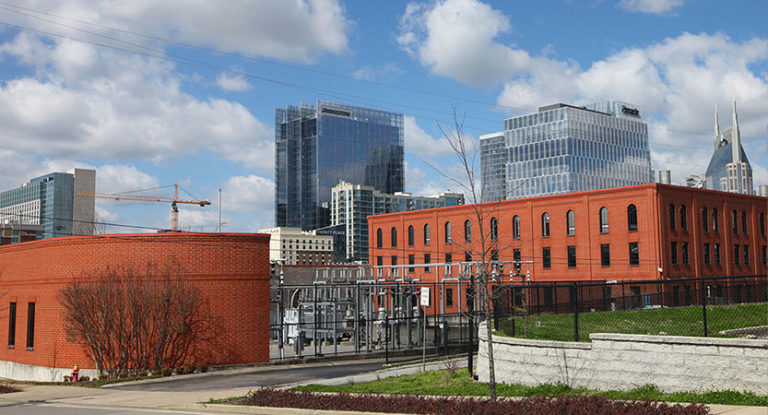
New service line extension to serve the new Music City Convention Center to serve 54,400 pph steam and 5,820 tons cooling,1,600 trench-feet of steam, condensate & chilled water distribution system expansion and new customer connection.
More Details About These Projects:
Berea College Central Plant and Distribution System
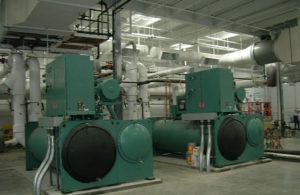
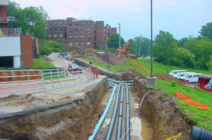 TEG provided the process design services as the prime designer of the Design/Build team selected by Berea College for construction of their new central plant that provides heating, cooling and future co-generation services for the College campus located in central Kentucky. The new central plant includes 1,500 tons of cooling capacity, 45 mmBTU/hr of hot water production capacity and provisions for two 2,000 kW engine generators for future co-generation capability. Approximately 12,000 trench-feet of hot water and chilled water distribution piping connects a majority of the existing campus to this plant with provisions for ultimately connecting all the campus buildings.
Detroit Thermal; Detroit, MI
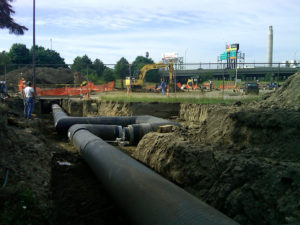
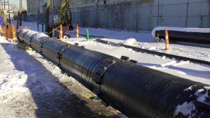 TEG provided technical support for the development, design and engineering for construction documents and construction administration of a major expansion of the Detroit Thermal district energy system. The design included a multi-phased pipeline construction as well as modifications to three boiler plant.
The pipeline originates within the co-generation plant operated by the district energy company and extends to a major manufacturing facility, including a new customer service connection. The new services, consisting of a 20″ high pressure steam main and 6″condensate return line, extend approximately 7,200 feet . The steam is primarily supplied from extraction steam from the co-gen facility where the system controls, process extraction, desuperheating and condensate systems required significant modifications. Backup steam is supply from a remote boiler plant within the district energy system. This facility was modified, including re-rating a 150,000 lb/hr boiler, required piping system modifications and auxiliary equipment modifications. Interface with the customer’s steam system required modifications to an existing boiler to facilitate backup operation and piping system modification to accommodate steam supply objectives.
Detroit Thermal; Detroit, MI
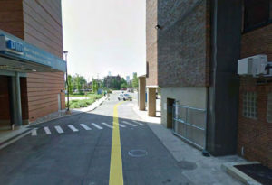 TEG provided the technical support related to the marketing effort to secure this important new district energy customer. After the successfully completion of the service agreement, TEG performed the design of the new steam service to the Rehabilitation Institute of Michigan (RIM) which is part of the Detroit Medical Center (DMC). To facilitate the new steam service, an existing 20″ high pressure steam main was relocated to accommodate a future DMC project and a new 8″ main extension was installed to provide serve the RIM and another planned facility. The steam service requirements for the RIM was designed for 30,000 mmBTU/h. The 6″ high pressure service line exits a new steam vault adjacent to the RIM and the steam line riser was installed external to the building and enters the ninth floor boiler room. The external riser was enclosed in siding to match the existing architecture upon completing the commissioning of the new service.
Metering and pressure reducing equipment was installed within the boiler room. TEG was be responsible for the interface with the Building’s engineer who is designing the modifications to the building’s thermal systems.
Entergy Thermal, LLC ; New Orleans, LA
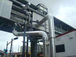
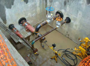 TEG performed the design services for Entergy Thermal, LLC (ETLLC) for the design of the new steam and chilled water services to the Louisiana Cancer Research Center (LCRC) constructed in New Orleans, LA. The new services was extend from the existing steam, condensate and chilled water mains suspended beneath the existing elevated pedestrian bridge that passes along the south end of the project site.
A new 8″ high pressure steam main, 4″ condensate return, 24″ chilled water supply and return mains were installed from the pedestrian bridge and transition to underground, extending north towards the site of a future development project. The LCRC service included a branch from the new underground piping that consisted of 6″ high pressure steam, 2″ condensate return and 14″ chilled water supply and return.
The service requirements for the LCRC are designed to provide 35,000 lb/hr of steam and 2,400 tons of cooling.
The service design included the installation into the building, through an interior vertical chase and extended to a 4th-floor mechanical room where steam and chilled water metering, steam pressure reducing equipment and chilled water energy transfer heat exchangers are installed. TEG was responsible for the interface with the Building’s engineer who designed the building’s thermal systems.
Entergy Thermal, LLC ; New Orleans, LA
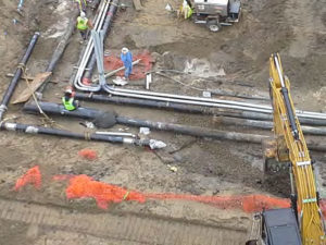
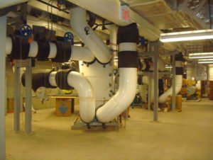 TEG developed the design and provided construction administration and surveillance services for the expansion of the existing Entergy Thermal, LLC (ETLLC) chilled water, steam and condensate return which serves the new University Medical Center (UMC) complex. In addition, hot water distribution piping was included on the UMC campus. The project was implemented in 4 phases consisting of the design of the underground steam, chilled water and hot water distribution system expansion; the design of the in-building heat exchanger equipment (energy transfer station) for two separate buildings and the design of a heat recovery chiller to provide both chilled water and hot water to the medical center.
The distribution system design includes approximately 3,500 trench feet of chilled water supply and return piping ranging from 24″ diameter to 10″ diameter; approximately 3,100 trench feet of steam and condensate piping ranging from 12″ diameter to 4″ diameter; and approximately 2,800 trench feet of hot water piping ranging from 12″ diameter to 6″ diameter; along with seven underground vaults. The in- building design services included steam, condensate return and chilled water supply and return from the piping entry the building from the underground distribution including metering.
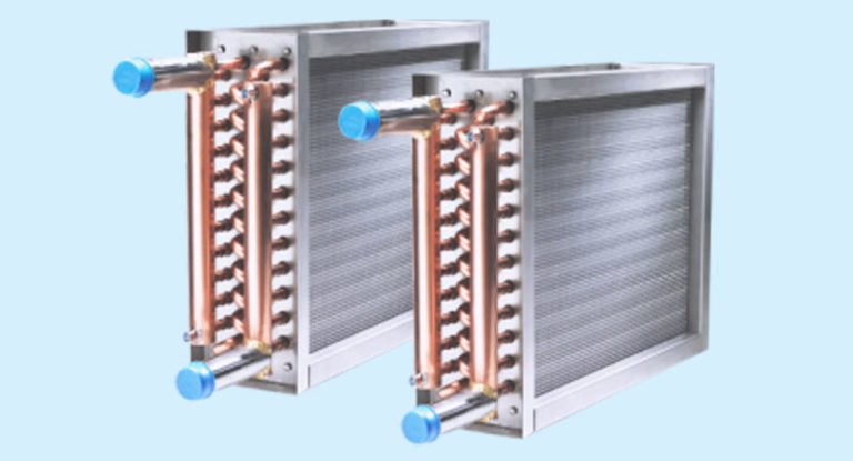
Chilled water system design involve both the design of the in-building piping from entry of the underground distribution system to the heat exchangers, and the heat exchangers themselves.
Steam system design involve both the design of the piping from entry of the underground distribution system through the PRV’s to the heat exchangers, and the heat exchangers themselves. Condensate system design included piping from the heat exchanger, including storage tank and pumps back to the piping from exit to the underground distribution.
The design also included chilled water supply and return and hot water supply and return to the heat recovery chiller (HRC) that was installed on the second floor of the UMC utility building. Early phase of the project included design and installation of the piping systems form the mains in the street up to the utility building and under the ground floor. Subsequent phases included design of the HRC installation and completing the chilled water supply and return and hot water supply and return from the HRC to the distribution system.
Design began in the late summer of 2012 and service to the facilities is to begin during late summer of 2013.
General Services Administration; Washington, DC
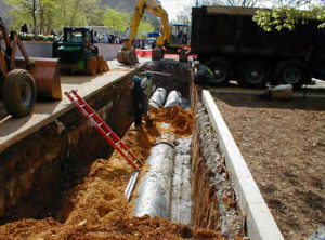
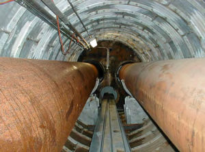 As part the installation of a 10.1 MW co-generation system with a 250,000 lb/hr HRSG and a 17,000 ton chilled water plant retrofit, TEG provided the development, design and construction services to complete the installation of 5,000 trench-ft of new 30″ and 24″ chilled water distribution piping with communication conduits. The design included integration of the existing chilled water distribution into the new piping and new piping to serve the Smithsonian museums on the south side of the National Mall.
To cross Independence Avenue the design included a 30′ deep shaft and 110′ tunnel. Once on the north side of Independence Avenue the distribution system extends east to serve several Smithsonian museums with chilled water from the GSA co-gen facility.
Service lines form the new mains included chilled water service to the Hirshhorn Museum, the National Air and Space Museum, the Air & Space Restaurant and the National Museum of the American Indian with provisions to provide chilled water service to 3 future facilities. The chilled water service included designing modifications to the in-building chilled water piping systems to interface with the new chilled water service. Typically the new service included new secondary pumps, new chilled water metering and provisions for stand-by and isolation of existing chiller.
General Services Administration & National Gallery of Art; Washington, DC
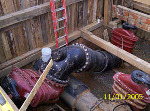
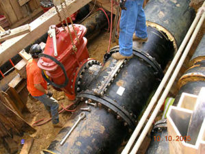 As part of a GSA CHP CW system expansion, 1,500 trench-feet of new 24″ chilled water distribution piping was installed to serve the National Gallery of Art (NGA). The engineering services included developing a hydraulic analysis to demonstrate the ability to adequately serve the new load. Upon completing the analysis and determining the required piping size, development of the pipeline routing and final engineering and design of the new main and services commenced.
The new main was connected to existing 24″ chilled water supply and return that was installed as part of the original GSA co-gen project and utilized wet tapping technology to avoid interruption of chilled water service to the National Air and Space and National Museum of the American Indian.
To adequately enhance the hydraulics of the chilled water distribution, an interconnection of the existing 20″ chilled water service to the Forrestal building with 30″ chilled water mains adjacent ot Forrestal (installed as part of the GSA CW system expansion) was designed and implemented. This improved the hydraulics at peak conditions and provided an alternate supply option for the distribution piping system. The design also included interconnection to existing chiller water piping within the NGA and metering of the new service.
General Services Administration & Smithsonian Institution AIB & Castle; Washington, DC
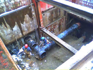 As an additional expansion of the GSA chilled water system TEG developed and designed the pipeline and in-building connections for the Smithsonian Arts and Industries and Castle buildings. The design include 1,500 trench-feet of chilled water distribution and building service connection. The existing chilled water piping system included service branch connections for these building as part of the original GSA co-gen project. These connections were within the tunnel shaft and the design included new metering with the shaft and line extension from the shaft.
Nashville DES – Metro Government of Nashville, TN
New service line extension to serve the new Music City Convention Center to serve 54,400 pph steam and 5,820 tons cooling,1,600 trench-feet of steam, condensate & chilled water distribution system expansion and new customer connection.

